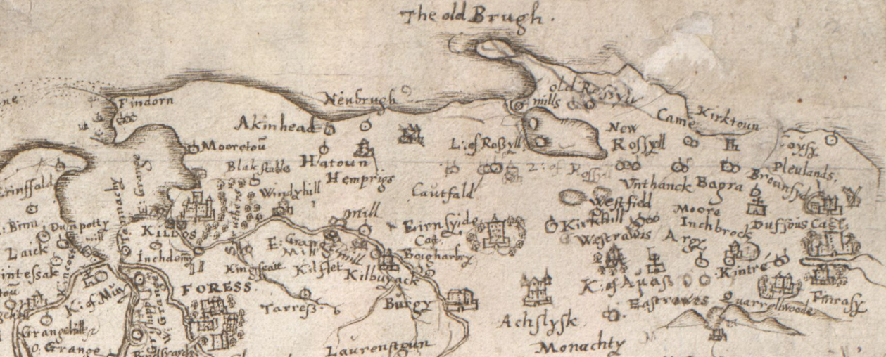
The manuscript map by the Rev. Timothy Pont circa 1590 shows a mill at East Grange but no details of it are known. Some information is available about its form in 1746 and of alterations made around 1898 when a third floor and a second pair of millstones were added.
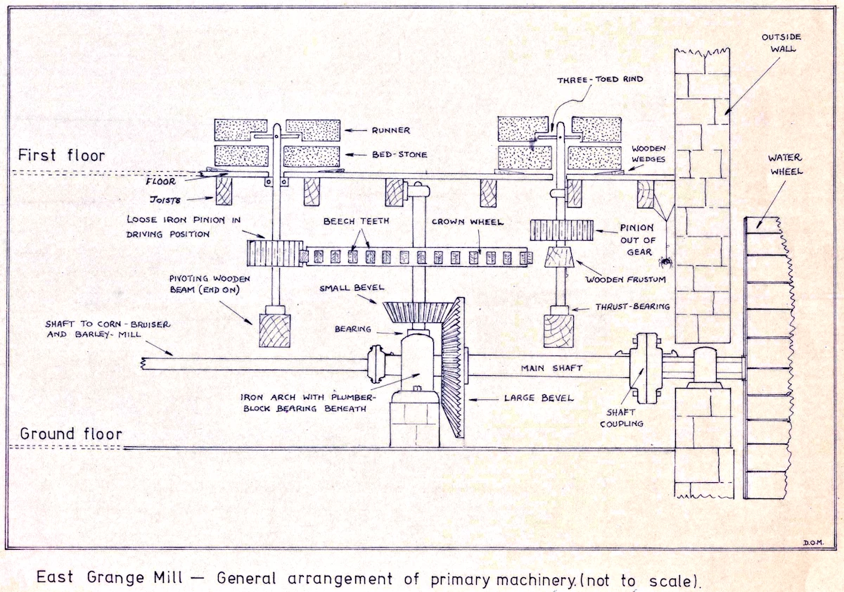
The milldam is fed by a stream flowing from the higher ground to the south and southwest, which changes its name as it passes through various estates, being known in turn as the Burgie Burn, the Grange Burn and the Kinloss Burn. There is sufficient drop in ground level between the dam and the mill for the water from the mill-lade to be fed via a wooden aqueduct to drive an overshot waterwheel 4.1 m. in diameter.
The wheel is made up of two circular, eight-spoked "spiders", to which are attached the rimplates supporting the buckets made of larch boards measuring 1.22 m x 0.31 m. The spiders are of cast iron and are one-piece castings with spokes of T-shaped cross section. The axle is of steel, octagonal in its centre portion, but square at the points where the spiders are mounted. It is supported on each side of the wheel by bearing journals and one end extends through the wall where it is bolted by means of a large flange on to the shafting inside the mill.
The wheel in its present state is no longer properly balanced and comes to rest with its heavy side at the bottom. This makes for a slight obstinacy when starting from rest. When constructed the wheel would have been made to run true by means of pairs of opposed wedges inserted between the spiders and the squared portions of the axle. This process was known as "staking" and involved the adjustment of thirty two wedges. In addition, when new, the wheel would be clean and all the buckets of the same weight, not some old and some new, as at present.
Inside the mill, the main shaft is supported at one end by the flange on the water wheel axle and at the other by a plumber-block type bearing, mounted on a masonry plinth. On the shaft, close to the plumber-block, is a large bevel gearwheel with 80 teeth; An iron arch astride the plumber block supports the lower bearing of a vertical shaft, the other end of which runs in a bearing in the roof. On the lower part of this shaft is a small bevel gearwheel with 28 teeth, meshing with the larger one on the main shaft and so converting the vertical rotation of the water-wheel into horizontal.
Immediately above the small bevel gear, the larger crownwheel is mounted on the same shaft. While the bevel gearwheels are castings with the teeth integral, the crownwheel has been cast with rectangular holes passing through the rim, tapering slightly towards the inside. Each of these holes or "pockets" holds a wooden gear~tooth, shaped from a block of beech. The inner ends of these blocks are notched and protrude beyond the inside of the rim. They are held in position by wedges driven into the dovetail formed between each pair of teeth, which pull the blocks firmly into the pockets. When "toothing" is
complete, the inside of the rim shows a continuous row of alternate tooth ends and wedges. There are 124 such teeth in the crownwheel. The millwright would dress the outer ends and flanks of the teeth so that the wheel had a constant radius and the drive was transmitted with a minimum of slip, backlash and noise. Beech was chosen for its ability to hold oil and for its toughness. The re-toothing and setting up of a crownwheel was considered to be two days work.
There are two sets of millstones in the mill and because they are similar in all respects, only one set will be described. Beside the crownwheel is a vertical shaft which turns the millstone on the floor above. It is driven by means of an 18-toothed cast iron pinion which can be meshed with the crown wheel. When in mesh this pinion locks down on to a wooden cone on the shaft and when not in use it can be slid up the shaft and wedged clear of the drive.
On the floor above sits the lower millstone or bed-stone, which does not move. The vertical drive shaft coming up from below passes through the hole in the centre of the bedstone and on top of the shaft is a metal support with three short arms arranged at 120 degrees to each other, known as the "three-toed rind". It is upon this that the top stone or runner sits, held clear of the bed stone, the shaft being supported by a bearing where it passes through the floor and the weight being taken by a thrust bearing at the bottom. This bearing does not rest on the floor but is mounted on a large wooden beam, one end of which is pivoted on the inside of the north wall of the mill and the other supported by a metal rod which passes vertically upwards through the ceiling to emerge just in front of the pair of millstones on the floor above. The last few inches of the rod are threaded and fitted with a large two-handed wing nut. By turning the nut the beam can be moved through a small arc thus allowing the clearance between the millstones to be adjusted.
The bed stone is levelled by adjusting the circle of wedges on which it rests and the runner stone is levelled on the three-toed rind by inserting strips of paper between the metal arms and the grooves cut in the stone to receive them. Given that the millstones are in normal use, the sheeling (de-husking) pair will need re-dressing with a mill pick every six to nine months, and the milling pair every five to six months. All the moving parts inside the mill, including the millstones are enclosed by wooden panelling and auxilliary drive is provided for other machinery, such as a bruiser.
The miller selects the speed of operation by controlling the flow of water over the mill wheel. In the aquaduct is a trapdoor, with its hinge-line on the downstream side of the gap. When the door is open, the water runs away down a chute and not over the wheel. When the door is shut, all the water coming down the aquaduct will pass over the wheel and do work. The trapdoor is controlled from inside the mill by means of a wooden lever mounted on a stand beside the millstones on the second floor. It passes through the window in the east wall so that from the window the state of the water and the door can be directly judged and controlled. Adjustment to the flow is made by inserting a pin into one of a series of holes in the lever spaced about 2.5 cm apart, so that the lever is held down against the weight of the door. These holes provide a coarse adjustment: for fine adjustment a long wedge tapering from 2.5 cm at one end to zero at the other can be slipped in under the pin so that, in the words of the miller, "The
amount of water can be set to within a cupful".
The miller, working at the millstones, has therefore all the information he needs: he sees his millstones, the water outside, the lever to control the speed of the mill, and he listens to the growl of the gearing downstairs for any variation which might indicate a need for adjustment - a useful guide when he has to leave his position to tend to the kiln or do other tasks.
(With many thanks to Sinclair Ross)